Swap-Space Management - ppt video online download
5 (308) In stock
Data Structures for Swapping on Linux Systems
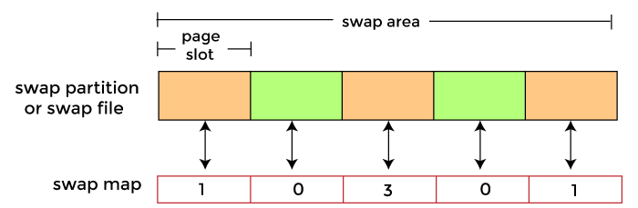
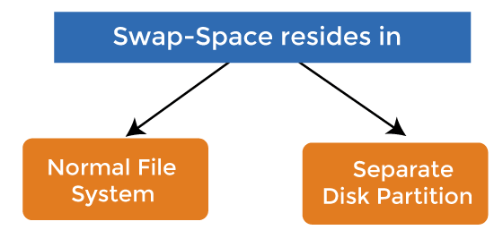
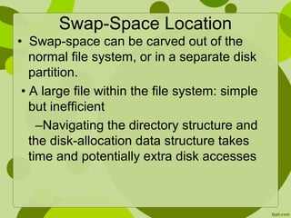
Swap-space — Virtual memory uses disk space as an extension of main memory. Swap-space can be carved out of the normal file system, or, more commonly, it can be in a separate disk partition. Swap-space management. Allocate swap space when process starts; holds text segment (the program) and data segment. Kernel uses swap maps to track swap-space use.
Mass-Storage Systems UCSB CS170 Tao Yang
Structure of mass-storage devices and the resulting effects on the uses of the devices. Hard Disk Drive. SSD. Hybrid Disk. Performance characteristics and management of mass-storage devices. Disk Scheduling in HDD. RAID – improve performance/reliability. Text book Chapter 12 and
Most popular: Magnetic hard disk drives. Solid state drives: (SSD)
Random access ~1000 times slower than disk. Mainly used for backup, storage of infrequently-used data, transfer medium between systems TB typical storage. Common technologies are 4mm, 8mm, 19mm, LTO-2 and SDLT.
SATA (replacing ATA, PATA, EIDE) SCSI. itself is a bus, up to 16 devices on one cable, SCSI initiator requests operation and SCSI targets perform tasks. FC (Fiber Channel) is high-speed serial architecture. Can be switched fabric with 24-bit address space – the basis of storage area networks (SANs) in which many hosts attach to many storage units. Can be arbitrated loop (FC-AL) of 126 devices.
SATA connectors SCSI FC with SAN-switch
Network-attached storage (NAS) is storage made available over a network rather than over a local connection (such as a bus) NFS and CIFS are common protocols. Implemented via remote procedure calls (RPCs) between host and storage. New iSCSI protocol uses IP network to carry the SCSI protocol.
Special/dedicated network for accessing block level data storage. Multiple hosts attached to multiple storage arrays - flexible.
Drives rotate at 60 to 200 times per second. Positioning time is. time to move disk arm to. desired cylinder (seek time) plus time for desired sector to rotate. under the disk head (rotational latency) Effective bandwidth: average data transfer rate during a transfer– that is the, number of bytes divided by transfer time data rate includes positioning overhead.
Moving-head Disk Mechanism
Disk Latency = Seek Time + Rotation Time + Transfer Time Seek Time: time to move disk arm over track (1-20ms) Fine-grained position adjustment necessary for head to settle Head switch time ~ track switch time (on modern disks) Rotation Time: time to wait for disk to rotate under disk head Disk rotation: 4 – 15ms (depending on price of disk) On average, only need to wait half a rotation Transfer Time: time to transfer data onto/off of disk Disk head transfer rate: MB/s (5-10 usec/sector) Host transfer rate dependent on I/O connector (USB, SATA, …)
Each reads one sector(512 bytes).
Seek: average 10.5 msec. Rotation: average 4.15 msec. Disk spins 120 times per second (7200 RPM/60) Average rotational cost is time to travel half track: 1/120 * 50%=4.15msec. Transfer: 5-10 usec. 54MB/second to transfer 512 bytes per sector. 0.5K/(54K) =0.01 msec. 500 * ( )/1000 = 7.3 seconds. Effective bandwidth: 500 sectors*512 Bytes / 7.3 sec =0.034MB/sec. Copying 1GB of data takes 8.37 hours.
Question How long to complete 500 sequential disk reads
Seek Time: 10.5 ms (to reach first sector) Rotation Time: 4.15 ms (to reach first sector) Transfer Time: (outer track) 500 sectors * 512 bytes / 128MB/sec = 2ms. Total: = 16.7 ms. Effective bandwidth: 500 sectors*512 Bytes / 16.7 ms =14.97 MB/sec. This is 11.7% of the maximum transfer rate with 250KB data transferring.
Question How large a transfer is needed to achieve 80% of the max disk transfer rate
0.8 (10.5 ms + (1ms + 8.5ms) x) = 8.5ms x. Total: x = 9.1 rotations, 9.8MB ( with 2100 sectors/track) A simplified approximation is to compute the effective bandwidth first. x/(10.5ms + x/128 ) = 0.8 *128 x=7.5MB. Copying 1GB of data takes 10 seconds!
Given a set of IO requests. Coordinate disk access of multiple I/O requests for faster performance and reduced seek time. Seek time seek distance. Measured by total head movement in terms of cylinders from one request to another. Hard Disk. Drive.
total head movement: 640 cylinders for executing all requests Disk Head. …
Selects the request with the minimum seek time from the current head position. total head movement: 236 cylinders.
Consider the following sequence of requests (2, 4, 1, 8), and assume the head position is on track 9. Then, the order in which SSTF services the requests is _________. Anthony D. Joseph. UCB CS162.
Q5: Consider the following sequence of requests (2, 4, 1, 8), and assume the head position is on track 9. Then, the order in which SSTF services the requests is _________. (8, 4, 2, 1)
SCAN: move disk arm in one direction, until all requests satisfied, then reverse direction. Also called elevator scheduling
total head movement : 208 cylinders.
CSCAN: move disk arm in one direction, until all requests satisfied, then start again from farthest request. Provides a more uniform wait time than SCAN by treating cylinders as a circular list. The head moves from one end of the disk to the other, servicing requests as it goes. When it reaches the other end, it immediately returns to the beginning of the disk, without servicing any requests on the return trip.
Algorithm Name. Description. FCFS. First-come first-served. SSTF. Shortest seek time first; process the request that reduces next seek time. SCAN (aka Elevator) Move head from end to end (has a current direction) C-SCAN. Only service requests in one direction (circular SCAN) SCAN (dumb elevator): Back and forth, to end/start track. C-: Circular: Only process requests in one direction. LOOK: Only go as far as last request.
SSTF is common with its natural appeal (but it may lead to starvation issue). C-LOOK is fair and efficient. SCAN and C-SCAN perform better for systems that place a heavy load on the disk. Performance depends on the number and types of requests.
Use NAND Multi-Level Cell (2-bit/cell) flash memory. Non-volatile storage technology. Sector (4 KB page) addressable, but stores 4-64 pages per memory block. No moving parts (no rotate/seek motors) Very low power and lightweight.
Limited by controller and disk interface (SATA: MB/s) Latency = Queuing Time + Controller time + Xfer Time.
Writing data is complex! (~200μs – 1.7ms ) Can only write empty pages in a block. Erasing a block takes ~1.5ms. Controller maintains pool of empty blocks by coalescing used pages (read, erase, write), also reserves some % of capacity. Anthony D. Joseph. UCB CS162.
Write A, B, C, D. Anthony D. Joseph. UCB CS162.
Write A, B, C, D. Write E, F, G, H and A’, B’, C’, D’ Record A, B, C, D as obsolete. Anthony D. Joseph. UCB CS162.
Write A, B, C, D. Write E, F, G, H and A’, B’, C’, D’ Record A, B, C, D as obsolete. Controller garbage collects obsolete pages by copying valid pages to new (erased) block. Typical steady state behavior when SSD is almost full. One erase every 64 or 128 writes. Anthony D. Joseph. UCB CS162.
Write and erase cycles require high voltage. Damages memory cells, limits SSD lifespan. Controller uses ECC, performs wear leveling. Result is very workload dependent performance. Latency = Queuing Time + Controller time (Find Free Block) + Xfer Time. Highest BW: Seq. OR Random writes (limited by empty pages) Rule of thumb: writes 10x more expensive than reads, and erases 10x more expensive than writes.
Bandwidth (Sequential R/W) Cost/GB. Size. HDD MB/s. $ /GB. 2-4 TB. SSD1, MB/s (SATA) 6 GB/s (read PCI) 4.4 GB/s (write PCI) $ /GB. 200GB-1TB. DRAM GB/s. $4-14*/GB. *SK Hynix 9/4/13 fire. 64GB-256GB. 1http:// 2http:// BW: SSD up to x10 than HDD, DRAM > x10 than SSD. Price: HDD x20 less than SSD, SSD x5 less than DRAM. Anthony D. Joseph. UCB CS162.
Low latency, high throughput (eliminate seek/rotational delay) No moving parts: Very light weight, low power, silent, very shock insensitive. Read at memory speeds (limited by controller and I/O bus) Cons. Small storage ( x disk), very expensive (20x disk) Hybrid alternative: combine small SSD with large HDD. Asymmetric block write performance: read pg/erase/write pg. Limited drive lifetime. Avg failure rate is 6 years, life expectancy is 9–11 years. Anthony D. Joseph. UCB CS162.
Q1: True _ False _ The block is the smallest addressable unit on a disk. Q2: True _ False _ An SSD has zero seek time. Q3: True _ False _ For an HDD, the read and write latencies are similar. Q4: True _ False _ For an SSD, the read and write latencies are similar. Anthony D. Joseph. UCB CS162.
Q1: True _ False _ The block is the smallest addressable unit on a disk. Q2: True _ False _ An SSD has zero seek time. Q3: True _ False _ For an HDD, the read and write latencies are similar. Q4: True _ False _ For an SSD, the read and write latencies are similar. X. X. X. X.
Time, Threshold, Loss of power/computer shutdown. Dram. Cache. NV. Add a non-volatile cache. ATA Interface.
Up to 90% Power Saving. when powered down. Dram. Cache. Read and Write instantly while spindle stopped. ATA Interface. NV. Cache.
Schroeder and Gibson. Disk Failures in the Real World: What Does and MTTF of 1,000,000 Hours Mean to You USENIX FAST Typical drive replacement rate is 2-4% annually. In 2011, spinning disk have 0.5% (1.7*106 hours) 1000 drives. 2%* means 20 failed drives per year. A failure every 2-3 weeks! 1000 machines, each has 4 drives. 2%*4000 = 80 drive failures. A failure every 4-5 days!
Mean time before failure (MTTF) Inverse of annual failure rate. In 2011, advertised failure rates of spinning disks. 0.5% (MTTF= 1.7*106 hours) 0.9% ( MTTF= 106 hours) Actual failure rates are often reported 2-4%. Mean Time To Repair (MTTR) is a basic measure of the maintainability of repairable items. It represents the average time required to repair a failed component or device. Typically hours to days.
Downtime per year. Downtime per month. Downtime per week. 90% ( one nine ) 36.5 days. 72 hours hours. 99% ( two nines ) 3.65 days hours hours. 99.9% ( three nines ) 8.76 hours minutes minutes % ( four nines ) minutes minutes minutes % ( five nines ) 5.26 minutes seconds seconds % ( six nines ) 31.5 seconds seconds seconds. Gmail, Hosted Exchange target 3 nines (unscheduled) 2010: Gmail (99.984), Exchange (>99.9) UnAvailability ~ MTTR/MTBF. Can cut it by reducing MTTR or increasing MTBF.
Multiple disk drives provide reliability. via redundancy. Increases the mean time to failure. Hardware RAID with RAID controller. vs software RAID.
Improve reliability by storing redundant data. Improve performance with disk striping (use a group of disks as one storage unit) RAID is arranged into six different levels. Mirroring (RAID 1) keeps duplicate of each disk. Striped mirrors (RAID 1+0) or mirrored stripes (RAID 0+1) provides high performance and high reliability. Block interleaved parity (RAID 4, 5, 6) uses much less redundancy.
Files are striped across disks, no redundant info. High read throughput. Best write throughput (no redundant info to write) Any disk failure results in data loss.
Mirrored Disks. Data is written to two places. On failure, just use surviving disk and easy to rebuild. On read, choose fastest to read. Write performance is same as single drive, read performance is 2x better. Expensive. (high space overhead)
Reads can go to either disk.
RAID 5 Files are striped as blocks. Blocks are distributed among disks. Parity blocks are added
Parity block: Block1 xor block2 xor block3 … block block block parity block. Can reconstruct any missing block from the others. Assume block 3 is lost. Block3 = block1 xor block 2 xor Parity. = xor xor
Read old data block. Read old parity block. Write new data block. Write new parity block. Old data xor old parity xor new data. RAID-5: to write entire stripe. Write data blocks and parity.
RAID 1: mirror data across two or more disks. Google File System replicated its data on three disks, spread across multiple racks. RAID 5: split data across disks, with redundancy to recover from a single disk failure. RAID 6: RAID 5, with extra redundancy to recover from two disk failures.
Then mirror of data blocks is striped on the second set. data disks. mirror copies. Stripe 0. Stripe 4. Stripe 3. Stripe 1. Stripe 2. Stripe 8. Stripe 7. Stripe 6. Stripe 5. Stripe 9.
Then stripe on a set of paired mirrors. Better reliability than RAID 0+1. Stripe 0. Stripe 4. Stripe 8. Stripe 0. Stripe 4. Stripe 8. Stripe 2. Stripe 10. Stripe 6. Stripe 2. Stripe 10. Stripe 6. Mirror pair. Stripe 3. Stripe 11. Stripe 7. Stripe 3. Stripe 11. Stripe 7. Stripe 1. Stripe 5. Stripe 9. Stripe 1. Stripe 5. Stripe 9.
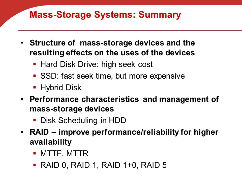
Structure of mass-storage devices and the resulting effects on the uses of the devices. Hard Disk Drive: high seek cost. SSD: fast seek time, but more expensive. Hybrid Disk. Performance characteristics and management of mass-storage devices. Disk Scheduling in HDD. RAID – improve performance/reliability for higher availability. MTTF, MTTR. RAID 0, RAID 1, RAID 1+0, RAID 5.

13. Secondary Storage (S&G, Ch. 13) - ppt video online download
Swap-Space Management - ppt video online download

PPT - Lecture 20 Ch. 12: Mass Storage Structure Ch 13: I/O Systems PowerPoint Presentation - ID:711181
:max_bytes(150000):strip_icc()/cloud-computing-4199287-f346729f8f574000a3058b9ad69e9a41.png)
What Is Cloud Computing?
Swap-Space Management in Operating System - javatpoint
Swap Space and Other Memory Management Issues Operating Systems: Internals and Design Principles. - ppt download

Swap PowerPoint Presentation and Slides
Swap-Space Management in Operating System - javatpoint
Swap space management and protection in os
Swap-space Management

PPT – FreeSpace Management PowerPoint presentation

OS- Operating Systems-TE CSE-IT- Swap space management

Swap PowerPoint Presentation and Slides

Virtual Memory Management - ppt video online download

PowerPoint History: Behind the orange icon
Buy Ad-On Mass Storage CrossFit Gym Equipment - 70'' | Vulcan Strength
How to Enable Mass Storage Mode on Android Device
Seagate Exos CORVAULT 5U84 Unveiled: Sustainable, Efficient Mass Storage for Media and Entertainment
 Semi-Precious Gemstone Bracelet. — DE VERA
 Roman Originals Women Denim Jegging Ladies Jean Leggings Stretch Trousers Pants
- Glamorise Womens Front-Closure T-Back WonderWire Underwire Bra 1246 Pink Blush 40G
 1Pair Imitation Silicone Hips Lifting Pad Insert Silicone Hip Hip Pad Butt Pads
 Baserange Rib Triangle Bra - Off-White
 Mustard Yellow Silk Lingerie Set, 100% Silk Bralette & Thong, Silk